Pennsylvania State University - 2016 to present
Space Missions

Sub-orbital rockets
Supporting technology

Lynx is the high-energy flagship mission concept funded for study by NASA for consideration in the 2020 Astrophysics Decadal Survey. Lynx will provide unprecedented X-ray vision into the otherwise “Invisible” Universe with unique power to directly observe the dawn of supermassive black holes, reveal the drivers of galaxy formation, trace stellar activity including effects on planet habitability, and transform our knowledge of endpoints of stellar evolution. These generational advances are enabled by leaps in capability over NASA's existing flagship Chandra and ESA's planned ATHENA. Lynx is a true next-generation X-ray observatory whose design will include excellent angular resolution, high throughput, large field of view, and high spectral resolution for both point-like and extended sources.
Lynx has three major science drivers:
The dawn of black holes - Lynx will look deep into the past and collect light from the first black holes in the Universe
The drivers of galaxy evolution - Lynx will observe the missing and most critical component in our understanding of how galaxies form and evolve
The energetic side of stellar evolution - Lynx will witness violent cosmic events and the origin of elements
I am an active member of both the optic and instrument working groups and offer expertise in alternative detector solutions and optical blocking filters.
The Off-plane Grating Rocket Experiment (OGRE)
I work with a group at the Pennsylvania State University, run by professor Randall McEntaffer, that is working on a sub-orbital rocket mission (OGRE). The payload of this mission is designed to test the effectiveness of off-plane gratings in a high resolution soft X-ray spectrometer. The goal of the mission is to show that such an instrument could improve understanding of shock fronts in supernova remnants and find the WHIM. My primary responsibility is to oversee the specification, design, fabrication, testing and launch of the X-ray CCD camera intended for the mission. In addition I assist in the integration and testing of the rocket spectrometer optics. A CAD model of the electronics section has been developed by XCAM and a CAD model of the X-ray optic has been developed by Will Zhang and his team from GSFC.
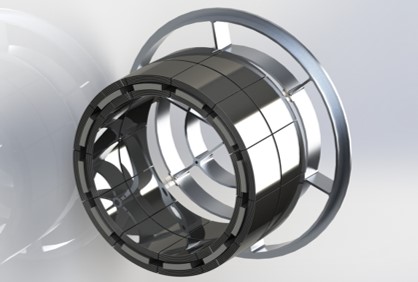
The optic is made from parabolic and hyperbolic silicon mirror pairs that are co-aligned onto supporting shell. The mirror pairs are mounted evenly above and below this shell before the complete structure is mounted onto a spider. This lightweight optic should be able to provide a PSF of < 5 arcseconds HEW.
CAD of the OGRE optic
The camera for OGRE is being designed, built, and tested by XCAM ltd and the CEI at the Open University. The camera is based around 4 teledyne-e2v CCD207-40 EM-CCDs, three are spectral and will detect diffracted X-rays and the central detector will sample the optic focus. Initially, the central EM-CCD will be used to confirm the pointing of the telescope in optical before using a filter wheel to switch to X-ray detection mode. The detector will be cooled to -100 °C using liquid nitrogen to minimize dark current and maximize multiplication gain.
cad of the camera chamber on ogre. left - camera chamber showing the three gate valves that isolate the camera from the rest of the payload. center - a side cut-though of the camera showing the cooling RESERVOIR and detector packages. right - the camera chamber with the top removed showing the detector positions
To readout the focal plane camera, a dedicated readout electronics system has been developed at XCAM ltd. and the CEI. The system uses 4 BeagleBone Black development platforms for the data readout and digital signal processing. For the spectral EM-CCDs, each detector is read out every 7.7 seconds and the frame is passed through a data processing pipeline. Upper and lower thresholds are set on each image and the X-ray events are identified and telemetered to the ground. Full frames are saved onboard.
For the central detector, each frame is read every 0.7 seconds. While operating in optical mode (neutral density filter used in filter wheel), a center-of-mass centroid is taken on each frame to show the location of the optical focus. If the location is off center from the center of the detector, commands are sent to the rocket to maneuver the centroid into the center of the image. The central 100 x 100 pixel region of the detector is telemetered to the ground. When moving to X-ray mode, the filter in the filer wheel is changed from a neutral density filter to an optical blocking filter. Operating in X-ray mode allows the PSF of the optic to be measured.
CAD image of the proposed ogre electronics section. the 4 em-ccd cameras are housed in the triangular chamber so that they can be evacuated and cooled. the right model shows a cutaway of the electronics section so that the inside of the boxes can be seen
Related Papers
Donovan - 2019 - An updated optical design of the off-plane grating rocket experiment
Donovan - 2019 - A comprehensive line spread function error budget for the Off-plane Grating Rocket Experiment
O’Meara - 2019 - The optomechanical design for the Off-plane Grating Rocket Experiment (OGRE)
Tutt - 2018 - The Off-plane Grating Rocket Experiment (OGRE) system overview
Donovan - 2018 - Optical design of the off-plane grating rocket experiment
Lewis - 2017 - The simulated spectrum of the OGRE X-ray EM-CCD camera system
Chan - 2017 - Kinematic alignment and bonding of silicon mirrors for high-resolution astronomical x-ray optics
Zhang - 2017 - Monocrystalline silicon and the meta-shell approach to building x-ray astronomical optics
Riveros - 2017 - Progress on the fabrication of lightweight single-crystal silicon x-ray mirrors
Lewis - 2016 - Development of the x-ray camera for the OGRE sub-orbital rocket
Riveros - 2016 - Progress on the fabrication of high resolution and lightweight monocrystalline silicon x-ray mirrors
Zhang - 2016 - Lightweight and high-resolution single crystal silicon optics for x-ray astronomy
DeRoo - 2013 - Pushing the boundaries of x-ray grating spectroscopy in a suborbital rocket
McEntaffer - 2013 - First results from a next-generation off-plane X-ray diffraction grating
Allured - 2013 - Analytical alignment tolerances for off-plane reflection grating spectroscopy
Bautz - 2012 - Concepts for high-performance soft X-ray grating spectroscopy in a moderate-scale mission
McEntaffer - 2011 - Development of off-plane gratings for WHIMex and IXO
Cash - 2011 - X-ray optics for WHIMex: the Warm Hot Intergalactic Medium Explorer
The Rocket for Extended X-ray Spectroscopy
The Rocket for Extended X-ray Spectroscopy (TREXS) is a sub-orbital rocket instrument that is designed to preform medium resolution soft X-ray spectroscopy over a large field-of-view. TREXS is based on similar technology to both OGRESS and WRXR, but with new technology designed to increase resolving power and effective area. The spectrometer on TREXS is based around three main components:
A passive focuser - TREXS is designed to have four distinct channels, each with their own dedicated passive focuser, The passive focuser is made up of a series of wire grids that have smaller and smaller wire spacing as you get closer to the focal plane. Only X-rays that are travelling along lines-of-sight through these slits will get through the focuser and reach the focal plane.
Reflection gratings - The dispersive element of the spectrometer. X-rays are diffracted with respect to wavelength. The location that the X-rays fall onto the focal plane is determined by the X-rays wavelength.
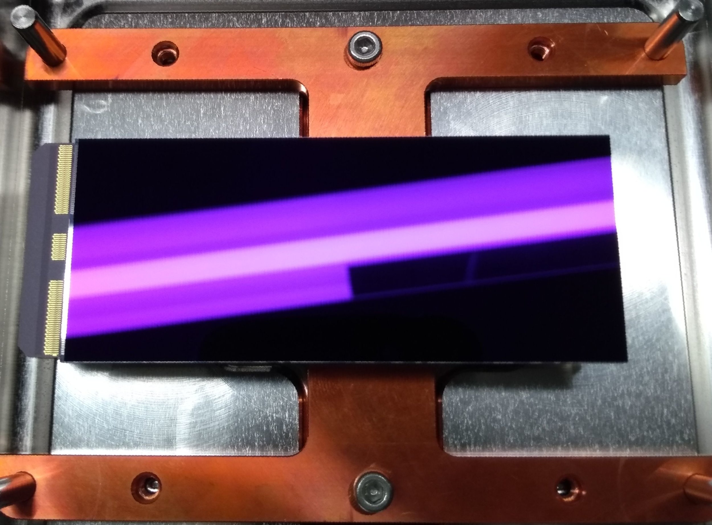
Focal plane camera - TREXS will use 11 teledyne-e2v CIS113 - Vega CMOS detectors on the focal plane.
enginering grade CIS113 Vega Cmos detector
Related Papers
Miles - 2019 - An introduction to the Rockets for Extended-source X-ray spectroscopy
Tutt - 2019 - The focal plane camera for tREXS
Optical Blocking Filters
To build effective X-ray instruments, technology that is able to reject optical photons while allowing X-ray transmission is required. Optical blocking filters using thin film aluminum are a technology that fills this requirement. Thin Al films are deposited onto highly transparent frames, normally with a polyimide supporting structure to help the filters survive launch.
This research aims to drive this technology forwards to maximize the effective area of future X-ray observatories such as Lynx. Silicon meshes are being designed to have > 90% throughput and steps are being taken to make the Al films thinner.
Grating Alignment
The grating alignment method developed at the University of Iowa was found to have some flaw. The first, and major concern was that the grating position was shown to be highly dependent on the temperature in the room while the epoxy was curing. If the temperature changed, so would the position of the grating.
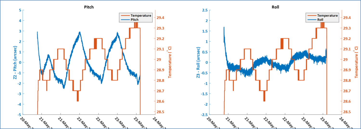
PLOTS SHOWING HOW THE PITCH (LEFT) AND ROLL (RIGHT) OF THE GRATING CHANGED OVER TIME WHEN THERE WAS A SMALL TEMPERATURE CHANGE IN THE CLEANROOM. SMALL CHANGES IN TEMPERATURE CAUSED MEASURABLE CHANGES IN PITCH AND ROLL
Better temperature control is imperative if we are to precisely control the alignment of the gratings. To control the temperature, a Praecis temperature control ATCU-5 unit was purchased. This unit is able to control the temperature in the enclosure to 50 times better than the control of the room.
Further upgrades are also planned to the Shack-Hartmann Sensor which will be replaced with an interferometer and to the module motion control which will be completed using a hexpod. These upgrades will not be in place for the WRX-R grating alignment campaign, but will be operational for OGRE.
The tolerance on the alignment of the grating for WRX-R are loose enough that the setup used in Iowa can be used. The tolerances are loose as WRX-R is a diffuse spectrometer and so high resolving power will not be possible.
Related papers
Tutt - 2019 - Grating alignment for the Water Recovery X-ray Rocket (WRXR)
Donovan - 2018 - X-ray verification of an optically aligned off-plan grating module
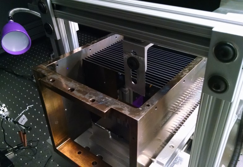
CAD showing the new alignment setup being used at penn state university. the new setup will be used to align gratings for WRXR
Future developments
Further steps are being taken to improve the accuracy of the grating alignment process and the speed at which the grating modules can be populated. These include:
Wedged gratings with direct silicon bonding
Uses the direct silicon bonding method being developed for the alignment of Silicon Pore Optics at cosine for ATHENA
Silicon gratings are wedged to fan the gratings, matching their position to the convergence of the X-ray optic, helping to reduce abberations
Wedged gratings with mechanical constraints
If direct silicon bonding is impracticable, mechanical constraints can be used
Precision machining constraints
Wire EDM is able to machine grating modules to high enough precision to use machined bosses to align the gratings
XMM-Newton RGS method
Precision machined surfaces are used to constrain the grating surface plane using spring clips